| Publication Type | Unpublished |
| Authors | Sherry Miller Hocking |
| Source | (1978) |
| Keywords | tool-text |
| Abstract | unpublished manuscript used as a studio manual at the Experimental Television Center |
An imaging system can be thought of in terms of three functions: image or signal generators, signal processors and signal controllers. Image, or more accurately signal, generators produce optically-based signals from cameras or non-optically based signals from oscillators. Image processors are devices which alter a signal from these sources in different ways; each processing module provides a means by which a single parameter or set of parameters of an image can be changed. Processing modules within a system are often arranged so that the output of one, a keyer, for example, can serve as an input for a second, for example a colorizer. Signal processors act on the signal after its initial generation and before its recording or display. The image or signal controllers often act on the processors; for example, a control voltage in the shape of a square wave may switch color changes in a colorizer from red to green. Further, some processing devices, such as certain colorizers and computer-based systems, are more accurately signal/image generators since they operate without external inputs.
Switching
Switching is a basic kind of signal processing from which other imaging techniques such as mixing and keying, or signal comparing, are derived. Switchers were the first commercially developed processing or "special effects" systems, appearing prior to the mid-1950s. The motivation for their development lay in the desire to switch or "cut" from one camera to another. Switching then can be defined as the serial presentation of image and/or sound derived from 2 or more sources and is achieved by the sequential changing from one input signal to another. As we will see, the term "serial" can be misleading; as the rate of switching is increased beyond a certain frequency, we no longer see one image following another. Instead the image we see might contain two or more source images simultaneously.
A switcher is a device which turns a signal on or off. It completes a circuit, allowing the signal to flow through a circuit from the input to the output. If the switch is on, the circuit is complete; if the switch is off, the circuit is broken, and the signal cannot travel from the input to the output.
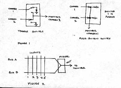
Switchers, then, have 2 or more inputs; the input signals, or images, may come from cameras or from oscillators or any other sync-compatible source. The switches in a switcher allow you to choose which of these inputs will be allowed to pass to the output, for example a monitor, at any one time. At its simplest level, a switcher can employ a mechanical switch, such as a toggle switch; by manually changing the position of the switch, the signal of one of the 2 inputs is allowed to pass because the circuit path is complete. In Figure 1, the switch position of camera 2 allows that signal to go to the monitor. A series of push-button switches works in a similar way; only one can be pushed at a time, and when it is pushed a circuit is completed between the input and output. In the push-button system of Figure 1, when button 1 is pushed, the signal from camera 1 goes to the monitor and the signal from camera 2 does not.
These mechanical switching systems illustrate a 2 input/1 output switcher. With a larger number of inputs, a multi-position switch might replace the toggle or on/off type; these have a number of on positions and eliminate the need to turn off an input before turning a second one on.
Many switchers also have more than one output; an example might be a multiple monitor matrix where each monitor displays a different camera image. As the number of inputs and outputs increases, these mechanical switching systems quickly become cumbersome. For example, if you have 10 inputs and 5 outputs and want any input to be available at any output, to be able to display any camera on any monitor, then you need 50 switches.
In general there are two kinds of switchers. In a " broadcast " type, there are any number of inputs and certain of them are permanently connected to a single specific output. Each bus is a series of inputs; in Figure 2 there are 5 inputs on each of the two busses, A and B, while one output is available. On each bus you can select one input; for example, on bus A you choose input 5 and on bus B you choose input 2. If the switcher is a push-button type, you can switch between 5 and 2 or any other combination of inputs by pushing the appropriate buttons. Only one signal comes to the output at any one time. If a fader is present before the output, you are then able to preselect a signal image on the A bus, one on the B bus and then fade between A and B; while the image from the B bus is then on the monitor you are able to select another image on the A bus and when you fade back t o A you have a third image on the monitor.
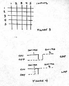
In the "distribution" type switcher, any input can be sent to any output. Because of the large number of cross-points, this system gets bulky and the problem is one of control. Manual switching of this large number of points would be time-consuming and confusing. Most image processing systems using distribution switching use a second system to electronically control these switching points.
The transition or timing of the switching is important. If you have to turn the first signal off before you turn the second on, as would be the case with a simple switcher using two position toggle switches, it is referred to as a gap switch. This type of transition will result in a blank screen at the point of switching as can be seen in the signal represented in Figure 4. If the first is turned off after the second is turned on, it referred to as a lap type or "make before break" switcher.
The point in time at which the switching occurs is also important and is directly related to the sync or timing of the incoming signal. Historically switchers began with simple switches; each camera was running on internal sync so there was no single common timing relationship among the camera inputs. Running on internal sync meant that each camera was beginning and ending its scanning process at a different time. Without a common external sync source insuring that all cameras began to scan their separate images at the same time, the output image would break up at the switching point. The switch could occur when camera 1 was 2/3 through the scanning process while camera 2 had just begun. The development of externally syncable vertical interval switchers prevented this picture disturbance. All cameras were externally locked to a common sync source, all beginning and ending their scans at the same time; with this it was possible to define and locate switch transitions at a point in time within the signal, called the vertical interval, which occurred at precisely the same instant for all camera inputs and which would be invisible since there is no picture information carried during the interval. Thus the problem of picture disturbance at the switching point was eliminated.
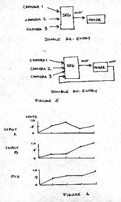
Up to this point we have talked about cameras or oscillators as switcher inputs; a single input can also be the output of another device, for example, an SEG or mixer, which themselves contain multiple inputs. When the outputs do not loop back and themselves become inputs to that output, the switcher is referred to as a "single re-entry" type. An example, shown in Figure 5, indicates 3 cameras as inputs to an SEG the output of which goes to a mixer, and that output is displayed. A "double re-entry" type indicates that the output of one device, fed to a mixer, is used as an input to that device; that input, then, potentially contains mixed or layered images of several cameras as a single image which can then be mixed again with the other single camera images.
Sequencing
A sequencer may be thought of as a specialized kind of switcher. The order of the switching can be repeated and is often programmable so that the series can be repeated indefinitely. The order is changeable so that the switching is not necessarily consecutive from input 1 through input 5, for example, but may be pre-programmed so that you can jump from one to another in any order and repeat that order. Sequencers also often contain a clock which controls the speed of the sequence. A signal pulse from the clock turns the first input off and next on when the level of the signal voltage reaches a certain point; the clock contains an oscillator the frequency of which can be changed, thus changing the speed of the sequencer. Sometimes sequencers have a specialized input for accepting a signal from an external clock. An external oscillator puts out a pulse which controls the speed of the sequencer. This type of device is referred to as voltage controllable because it takes in a signal from another device and uses it to control a parameter of image processing, in this case the rate of sequencing. Sequencers can be banked or cascaded, that is, arranged in a configuration where the output or clock of the first triggers the second.
Switching thus began as a technique for cutting among a number of video images and thus allowed a number of points of view to be presented sequentially. Switching and sequencing are integral to video because they function within the timing limits of video imaging. As techniques of image processing they are frequently used with "real time" images. In contrast, editing presumes that the images are recorded. If the switcher is able to accept videotape recorders as inputs, this sense of "real time" sequence may be false, since "recorded time" events are intercut with live events.
Mixing
Mixers were developed in the 1950s as special cases of switchers. As with switchers, mixers used 2 inputs, but the images were combined in an additive way rather than an either/or way. In a mixer, the input image signals are added together and then, in effect, divide or scaled down so that the resulting signal output is within the prescribed limitations of signal amplitude. Mixing happens in "real time" so that the output is the instantaneous sum of all the instantaneous amplitudes for each point along each horizontal line of the inputs. Because the 2 inputs are synced to an external source, they begin to scan at the same time; as scanning occurs, each signal contains a series of instantaneous voltages or amplitude levels corresponding to the gray values in the scenes. The voltage levels for each point along the horizontal line are then added together, producing an output signal containing information from both inputs. As the lines are built up into fields and frames, the resulting image is a mix of both source images. Figure 6 illustrates the process. Mixers thus provide the means for the development of superimposition.
Mixers often contain slide pots which attenuate or vary the "amount" of the input signals which are added together. Fading then is a variation on mixing and switching. Rather than an abrupt or instantaneous cut or switch from one signal to another, fading allows a gradual increase or decrease in signal levels, resulting in an image containing elements of 2 inputs with one becoming increasingly predominant (fade in) while the other either remains (superimposition) or gradually disappears (fade out). With the slide pots, the input signal voltage presently on is decreased in amplitude, while the off input signal voltage is increase in amplitude. In a "lap dissolve", both images are superimposed for a time while one is decreased and the other increased; in a "fade in/out" the first is gradually reduced to zero amplitude (no image) before the second is gradually increased, so no superimposition results.
So far we have talked about switching which occurs during the vertical interval of the signal and at a rate which is slow enough for the perceptual system to register two or more discrete images being sequenced in time. Obviously video is capable of switching at rates much faster than these. Superimposition will appear if the rate of switching is faster than about 1/10 second, even though discrete images are presented. In this case superimposition appears because the speed of the switching is more rapid than the eye can resolve as a sequence of discrete images rather than resulting from the mixing of image signals by a mixer/fader device.
Wipes can be thought of as switching within the frame. They appear as stationary or traveling horizontal or vertical divisions of the screen into two or more areas each containing the corresponding portion of the input image.
If you have 2 input images, each source locked to a common sync source so they begin scanning at the same time, and you switch at a point half-way through the scan of all the horizontal lines, the result is a horizontal wipe, an image divided in half horizontally, the top half containing the top of image A and the bottom the bottom half of image B.
Obviously you can control the point of switching so you can vary the proportions of rectilinear division. At a still higher frequency of switching, you can produce a second horizontal division, putting A in the top and bottom thirds and B in the center. As the frequency increases, so do the number of horizontal divisions. The output signal scans A, switches to B, back to A, back to B, and so on for the duration of the frame. The wipe device is "counting" horizontal lines and switches to a second input after a specified number of lines or time duration has passed.
If instead of switching after the completion of a number of complete horizontal lines, you switch mid-way through the scan of each line, the result is a vertical wipe, an image divided in half vertically, each side containing the corresponding portion of the image from the input. The scan for the first horizontal like of input A begins but switching occurs before it is completed; the output signal for that line then contains the first half of input A and the second half of input B. If this process is continued for the frame, a vertically divided image results. Because we are dealing with the horizontal line frequency of over 15,000 cycles per second, the switching frequency for this kind of wipe is much higher than the horizontal wipes. The principle is the same, and the screen may be divided into vertical bars, each containing segments of the input image. Both horizontal and vertical wipes are produced by a switching device which "counts" from one side toward the other (vertical wipe) or from the top downward (horizontal wipe) for a specified amount of time and then switches to another input before the scan has reached the other side or the bottom. The addition of pots again allows you to change the "counting" dynamically in real time so traveling horizontal and vertical wipes are produced. By adjusting horizontal and vertical wipe functions at the same time, rectangular or corner wipes are created.
Comparing
Keying is another important imaging technique which is based on switching. It involves cutting a hole or window in an image so that corresponding portions of a second image appear in the hole. Because the hole, in monochromatic keying, is defined by a gray value, the hole will have different shapes depending on the spatial locations in the image which contains the specified gray value. The hole is created by a threshold voltage level which falls somewhere between 0 and 1 volt, the acceptable range for black and white video signals. The camera signal voltage as it comes in is compared with this threshold voltage and at every point where the camera signal exceeds this threshold, the video is eliminated. As the video is eliminated, the keyer switches to a second input signal. In keying the switching process occurs within the image rather than between "whole" images. It occurs within each horizontal line rather than between fields or frames. It is then high speed switching which occurs in real time, point by point, for each horizontal line.
The basis of a keyer is a comparator circuit, a digital switch which has two states, either on or off. It has two inputs and one output. The inputs, for example cameras have voltage levels which continually vary within the 1 volt range, and the output is either on or off. The output state is determined by comparing the two voltage input levels. The process of comparison is very high speed because the comparator continuously compares the input values during each scan line. If one of the inputs of a comparator is a camera and the second is a signal of fixed value, a keyer results. If the voltage from the camera goes above the fixed threshold value, the output is on; when it falls below the threshold, the output is off. In this way, the hole is created, but in this comparator there is no means of inserting another image into the hole we have created.
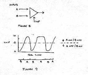
To insert portions of a second image into the holes created, we need to add to the comparator an input which we can use as our reference signal for determining the timing of the switching. We can then use A and B inputs for two camera images and the "clip" as the reference, as in Figure 8. In the previous example, we used the B input as the threshold for determining switching; in this example, B was a steady-state voltage, although we could have used a camera signal as input. With the addition of the third, the clip, input we can switch between A and B, the timing of the switching being dictated by the value of the voltage from the clip input. The clip sets a voltage level or gray value which determines when the keyer switches from A input to B input. The clip can be a steady-state voltage which can be varied between 0 and 1 volt by adjusting a pot. The clip can be a signal from an oscillator, a sine, square or triangle waveform or a complex waveform signal already constructed from other basic waveshapes. Or the clip can be a signal from one of the two video inputs or a third camera.
In Figure 9, assume a steady-state clip voltage of .5V and an input A signal which varies. At each point along each horizontal line the A voltage is compared to the clip; if A exceeds the clip level, A is on; when the A voltage falls below the clip level, then the keyer switches to the B signal. Because the clip level is adjustable, the threshold for switching changes resulting in various spatial combinations. Keyers frequently contain a reverse function which merely reverses the switching; in the above example, if A exceeds .5V then A is off rather than on.
Imagine that the A camera input is a series of concentric rectangles, the central black (.1V), the next dark gray (.25V), the next light gray (.75V) and the last white (1V). B camera input is black diagonals, producing a horizontal waveform of a square wave. Assume the clip is .2V and that below this level A is on and B off. At this setting only the central black rectangle from A appears, surrounded by the diagonals from B, because all other signal levels from A are above the clip level. If the clip is set at .5V, the dark gray rectangle is added, and both are surrounded by the diagonals. As the clip level is moved toward white, then more of the gray rectangles appear.
If we reverse the process, setting the clip at .2V, and below the clip B is on and A off, a very different image set appears. In this case, the black rectangle is dropped out and replaced with diagonals from B input. As the clip level voltage increases, the dark gray rectangle is replaced finally with the light gray.
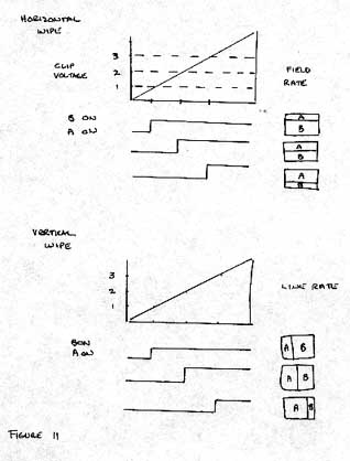
As noted, periodic waveforms from oscillators can also be used as clip inputs. If the clip input is a ramp signal at field rate, or 1/60 second, then each field is divided horizontally between A input and B input, as shown in Figure 11. As the voltage level of the clip is gradually increased, there is an increase in the length of time A is on and consequently in the number of lines from the A image that are traced before the keyer switches to B, resulting in different divisions of A and B.
If the clip input is a ramp signal at horizontal frequency (15,750 Hz), then each line would be divided between A and B and a vertical wipe results. Combining the horizontal and vertical square waves produces rectangles.
In the same manner, mixing vertical and horizontal ramps for the clip produces a diagonal division, vertical and horizontal sine waves produce a circle and horizontal and vertical triangle waves produce diamond shapes. The principle of mixing these waveforms and the resulting shapes is that of the additive combination of oscillator signals. The difference is that the result is not purely formal geometric, non-optical images but rather one which contains two input images in those formal patterns. Commercially produced equipment normally has these various patterns hard-wired into the boards. The important concept is that they can be produced by using the basic building blocks of periodic waveforms and keyers. The advantage of the commercial production system is the speed at which pre-determined wipes are available. But by combining periodic waveforms to produce asymmetric shapes, one can produce an almost infinite variety of wipe patterns.
A number of keyers can be banked or cascaded together; they can be operated independently of each other or the output of one can become an input for another. In this way, extremely complex, layered imagery can be constructed. Keyers frequently are voltage controllable; rather than increasing or decreasing the clip level by manually changing a knob setting, the clip level is changed by a signal voltage from another source. For example, if you wanted to key out portions of the image progressively from black to white at a constant rate and then stop, a ramp wave from an oscillator could be used as the control signal. The keyer may have a selectable hard/soft edge function. In the hard edge keyer, the switching point produces a clearly delineated edge between images A and B; in the soft-edge keyer, the separation is electronically "blurred" at the switching point resulting in a softer effect.
A chroma keyer functions by the same principles as a monochrome except the clip which determines the switching point operates on a specific color value rather than a gray value. Although in broadcast situations, the chroma keyer often drops out a blue hue, any color could be used.
The imaging techniques of mixing, fading, superimposition, keying and wiping are all based on the process of switching. Switching presumes a number of inputs, one of which is on while the others are off. If the switching occurs at a slow rate, the presentation of discrete images is serial; if the rate is high enough the presentation is simultaneous. The output images can thus be fractured by the primary horizontal and vertical divisions, as well as other regular and non-regular patterns. If the input images are equally mixed without changing their proportional addition through the time base of image formation, the referent is static and superimposition occurs. If the proportions change through time, the referent is dynamic and a fade results. Layers merely compare an input signal to a reference signal and switch between inputs.
Using these techniques enables a spatial fracturing of the picture plane which is actually created by a rapid switching between or among images as they are constructed through time. It is this temporal aspect of switching which allows the spatial reorganization of imagery. Disparate images can be combined and possess technically logical relationships as a whole, yet call into play ideas of scale, perceived reality and our sense of "real" time and space. These techniques as they have been employed in video have frequently been compared to Cubism, in their simultaneity of presentation of points of view, to the Suprematists, in particular Mondrian, with their use of purely geometric and often rectilinear formal properties, and to Surrealism, in their careful combination of logically dissimilar and impossible though seemingly realistic imagery. When live imagery is combined with pre-recorded events simultaneously, our understanding of "real" time and its apparent serial and progressive nature is challenged.